
Roll-up slim jim antenna build with Michael Boatright, KO4WX
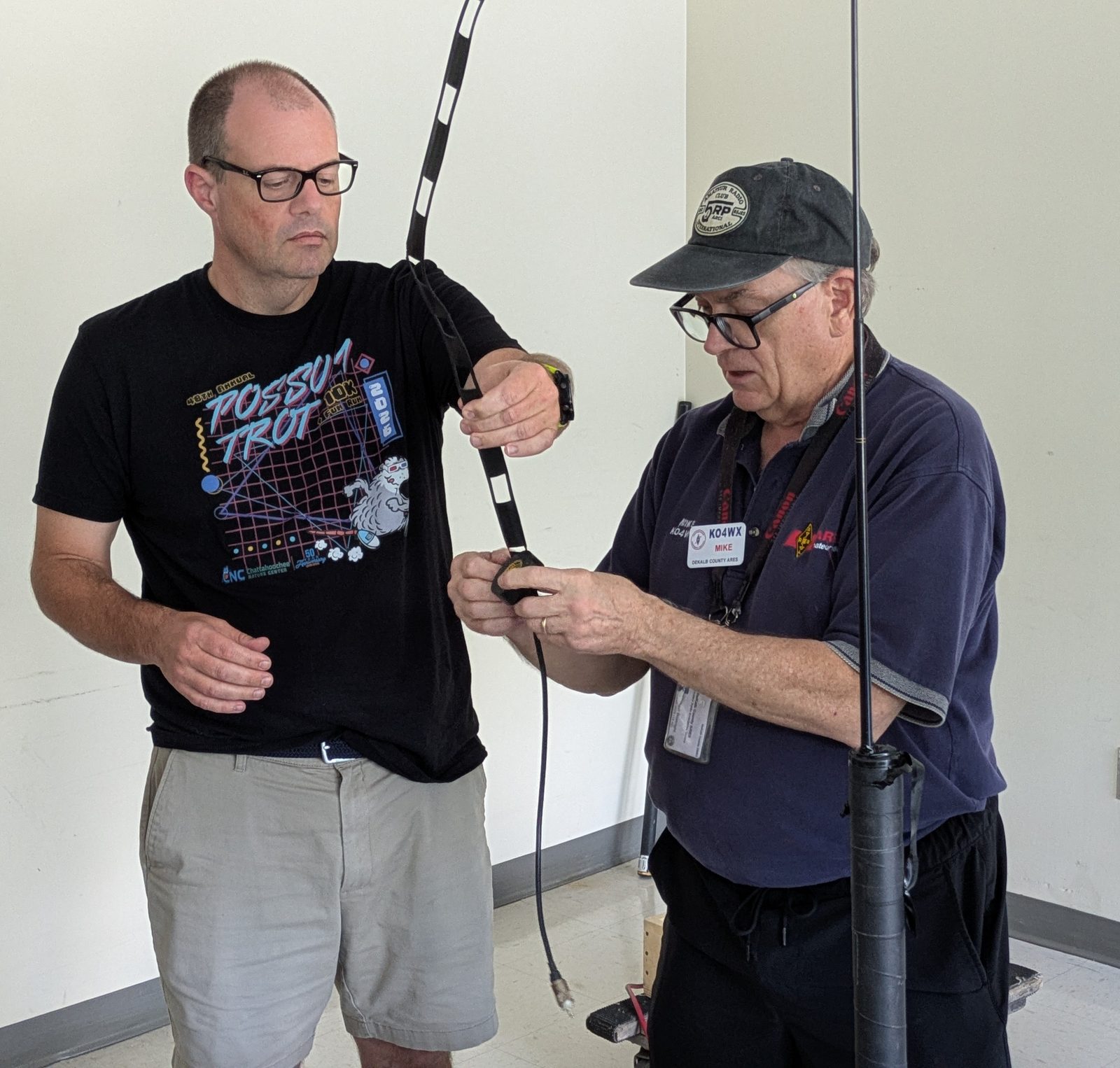
Michael Boatright (KO4WX) walked DeKalb ARES members through building a 2 m roll-up slim jim antenna out of 450-ohm window line, including crimping the PL-259 and tuning the feedpoint. A cheap, packable antenna that turns an HT into a far more capable station in the field.
At the July monthly meeting, Michael Boatright (KO4WX) showed members how to build a 2 m roll-up slim jim antenna, start to finish. The build is one of the best value-per-dollar upgrades in a go-kit: a few feet of 450-ohm window line, a length of RG8X, and a PL-259 turn into an antenna that rolls up to nothing and dramatically outperforms the rubber duck that came on your HT.
Why a roll-up slim jim belongs in your go-kit
A stock HT antenna is a compromise. It is short, it is electrically inefficient, and it is usually sitting at waist height next to a body that absorbs a good part of what it radiates. The slim jim fixes most of that at once:
- It is a real half-wave radiator, end-fed and matched by a quarter-wave stub, so it needs no ground plane. That matters when you are hanging it from a tree limb rather than bolting it to a truck roof.
- Height is the whole game on VHF. Because it is a limp piece of window line, you can hoist it up a mast, throw a line over a branch, or tape it to a tent pole. Getting the antenna 20 feet up does more for your signal than almost any radio upgrade.
- It rolls up. The finished antenna coils into a sandwich bag and weighs almost nothing, so there is no excuse to leave it home.
- It costs a few dollars and is repairable in the field with a knife and some tape.
For an ARES operator that adds up to a practical answer to the most common field problem we have: you can hear the repeater, but the repeater cannot hear you.
The build
Mike covered the whole sequence: cutting and stripping the window line, forming the stub and the gap, soldering the feedpoint, crimping the PL-259 onto the RG8X, and then tuning the result with an antenna analyzer.
The reference build members are working from is Mindy’s writeup at km1ndy.com, which uses roughly 5 feet of 450-ohm window line and gives the dimensions from the M0UKD calculator at an 89.8% velocity factor:
| Segment | Length |
|---|---|
| A, 3/4 wavelength (overall) | 141.4 cm |
| B, 1/2 wavelength element | 92.9 cm |
| C, 1/4 wavelength stub | 46.4 cm |
| E, gap between elements | 2.1 cm |
The one number you should expect to fight is the feedpoint distance. The calculator suggested 4.6 cm up from the bottom, but the actual build needed roughly 8.8 to 9.8 cm to land a usable match. That is normal, and it is the whole reason an analyzer is part of the build rather than an afterthought: the calculated numbers get you close, then you move the feedpoint until the VSWR dip sits where you want it. Done right the antenna holds VSWR under 2 across most of the band, with a coax choke at the feedpoint to keep RF off the outside of the shield.
If you want to brush up on the connector half of the job, the group covered PL-259 and cable work in more depth at the May 2024 connector installation session.
Try it yourself
The parts list is short enough to order in one sitting, and the build is a good rainy-afternoon project. Bring the finished antenna to a weekly net and see what it does for your signal into the repeater compared to your handheld’s stock whip. If you want help with the tuning step, ask on the Groups.io list and someone with an analyzer will almost certainly offer.